Media Maker's Lab | Joystick Controller[ Projects ] [ Workshop Resources ] [ Workshop Photos ] [ theoryofpaul.net homepage ] The idea of the joystick controller is to provide a way to exhibit the work of an entire class of students, who are learning how to patch. The entire system costs less than $100, and constists of:
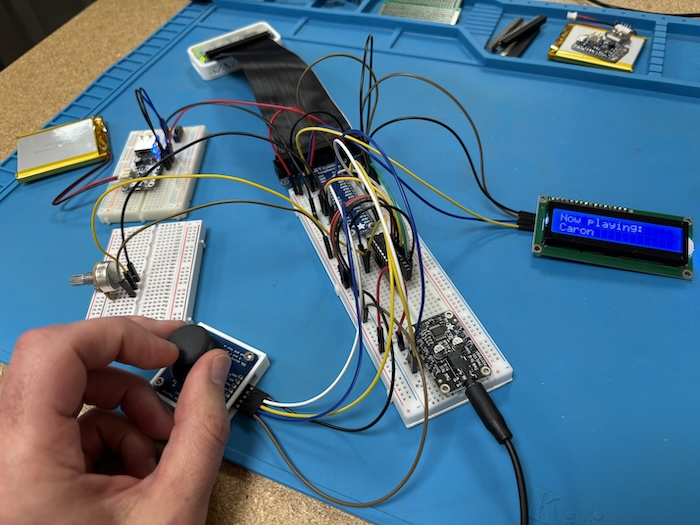
The Pi Zero runs a standard installation of Debian Linux, with Pd (Pure Data) running on the board itself. A Python script sends joystick and potentiometer data via OSC to Pd; in turn it receives a string variable -- the name of the student's patch -- and sends it out to the LCD screen. The joystick button cycles through students' patches, which all take two variables (x and y position of the joystick) and do anything with them in the audio domain. Adding student patches to the main patch is extremely easy since they are all simply subpatches within the main patch. The joystick button just increments a counter, which routes data through each subpatch in turn. Then the audio gets sent to the UDA1334a (which is configured as an audio output device in /boot/firmware/config,) and the student's name gets sent via OSC out to the Python patch (which in turn formats it and sends it to the LCD screen). We are currently working on constructing a PCB board so we can mount all the components, connect them, and house them in a 3D printed enclosure easily. Content on this page is licenced under GNU General Public License. |